Kestrel EMT
Program Structure
Kestrel EMT is broken into three software components.
Kestrel Circuit Editor – Full featured circuit creator
Kestrel Solver Core – Transient Solver Engine
KPlot – Fast plotting and analysis tool for Kestrel EMT .hdf5 result files and other formats including: Siemens PTI PSSE .out, PSCAD .inf, KGRID .raw, Comma-Separated Values .csv
Three executables are provided with the default installation of Kestrel EMT:
Kestrel.exe - Contains both the Kestrel Circuit Editor and Kestrel Solver Core
KestrelCLI.exe - Contains only the Kestrel Solver Core and a simple interface for running .kcf files
KPLot.exe - The plot tool
Components
There are multiple components available for simulation, including:
Passive RLC elements
Transmission line models
Power electronics components such as switches and diodes
Mathmatical blocks for sensing and control systems
MATLAB and Python blocks to input arbitrary control or analysis code
Components are broadly broken up into Circuit, Math, and Other blocks. Circuit blocks are solved by the core network solver using numerical integration. Math blocks are solved separately from the network solver. Some special blocks, such as the node monitors, Python, and MATLAB blocks are grouped in the Other category.
Creating Simulations
In Kestrel EMT, you may construct electrical circuits using Circuit blocks and perform additional mathmatical calculations using Math blocks.
Sample circuit files (.kcf files) are provided in the installation directory (by default C:/Program Files/Kestrel/sample_kcf). Please copy the files out of this directory before attempting to read or write to them.
Creating Your First Simulation
Upon opening Kestrel EMT, you will have a blank canvas that is labeled NewCircuit. Use the hotkeys shown in the Quick Help (if it is hidden you can show it again by pressing the Quick Help button in the ribbon) to place components, or double click the component you want in the Picker to the right.
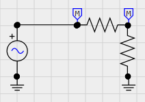
Start by finding the following components in the Picker on the right, and place them on the canvas: (2) Resistors, Voltage Source, (2) Monitor Node, and (2) Ground. (Hotkeys R, V, and G respectively)
Next connect the components as shown in the figure. a. To rotate components, select a component and press CTRL+R (or press the Rotate button). b. To connect components together, either connect their nodes directly (like the two resistors) or connect them using a wire (hotkey W). c. Place one Monitor Node between the two resistors and one between the resistor and voltage source. This will monitor the voltage at that node and we will be able to see it in the plot later.
Select one of the resistors and change the resistance to something other than the default 1000 Ohms, using the Properties panel to the left.
In the ribbon, configure the time step to be 50 us and duration to be 100 ms.
Press the Run button. You will be prompted to save the circuit.
The simulation should execute quickly and display the KPlot plotter.
In KPlot, check the checkboxes in the left column to display your monitored voltages.You should now see time varying sinusoids that illustrate your voltage divider!
You’ve completed your first EMT simulation! All Kestrel EMT simulations build from this– adding components to the canvas, configuring them, and pressing Run to execute the simulation.
Circuit Block Tips
Circuit nodes in Kestrel EMT may either be three phase or single phase. Three Phase nodes are denoted by thick wires and the tri-colored node symbol. Single Phase nodes are denoted by thin wires and a black node.
Math Block Tips
Basic mathematical blocks are included in Kestrel EMT for putting together easy to read digital logic and math-based controls.
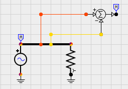
The inputs to Math blocks may be interfaced directly with Circuit Nodes. This will pass the voltage at that node to the Math block. Outputs to math blocks cannot be connected to circuit nodes. For example, see the simple example below where the A-B line to line voltage of a three phase circuit is measured.
The math engine is implemented separately from the network solution and is solved at the end of the simulation loop. As a result, any math blocks that feed back into the network solution will only be reflected after a single timestep delay.
Feedback between Math blocks is not supported yet, in other words, you cannot loop the output of a Math block into a block that (eventually) feeds into that same block. As a result, it is recommended to implement control systems with feedback in Python code blocks.
Math inputs left floating will be set to a constant of 0.
Internally, Kestrel EMT uses floating point numbers for all calculations. This includes blocks that simulate digital logic such as the AND, OR, and NOT blocks. A floating point value of 0.5 or above is considered True.
Circuit Block Tips
You may break three phase connections into single phase connections by attaching Phase A, Phase B, or Phase C wires to a three phase connection or wire.
If a Single Phase wire is connected to a Three Phase wire, the Single Phase wire will automatically connect to Phase A.
The ground symbol will ground a single phase or all three phases, depending on the connection.
\pagebreak
Python Block
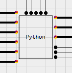
The Python block (under “Other”) allows for flexible development of control code and interfacing between Kestrel and other software tools. During the simulation, the Python block will execute its code within the provided Python 3.8 environment. Once per timestep, the function func() will be called. The function signature should match the number of specified inputs and outputs. For instance, the Python block in the figure is configured to have 23 inputs and 12 outputs. Thus the function signature should look something like this:
def func(x1,x2,x3,x4,x5,x6,x7,x8,x9,x10,x11,x12,x13,x14,x15,x16,x17,x18,x19,x20,x21,x22,x23):
	# user code
	return y1,y2,y3,y4,y5,y6,y7,y8,y9,y10,y11,y12
def sim_end():
	# user cleanup code
	return
Optionally, you may also specify a sim_end() function, which will run at the end of the simulation (whether the simulation was successful or not). This is useful for placing any clean up code you need to run once at the end.
Users may also specify the Call Rate, which determines how often the code is called if less than every timestep is desired.
Python blocks do not share variables or scope by default. However, you may choose to do this by unchecking the “Auto” textbox in the Python Scope parameter and inputing a named scope. Python blocks that share a named scope will share variables and function names.
Though the GUI has a limit to the number of inputs and outputs available for Python blocks, the Numerical Core itself (and CLI) supports up to 255 In and a practically unlimited number of outputs. This may be configured in the NetList element of the KCF file corresponding to the Python block. Update the NumInputs and NumOutputs and add as many Terminal elements as needed. Note that the all Inputs must be listed first, then all Outputs must be listed.
Matlab Block
MATLAB 2024a or above is required to use this block. The Matlab Block (under “Other”) is similar to the Python block in that it interfaces externally with MATLAB to execute code within the block. To use this block, you must have MATLAB installed on your machine.
NOTE: YOU MUST CONFIGURE YOUR SYSTEM PATH ENVIRONMENT VARIABLE TO USE THE MATLAB BLOCK. SEE BELOW.
Kestrel needs to know where to find the MATLAB Engine libraries to work. To do this, you’ll need to modify your system PATH environment variable. To do this in Windows, follow these steps:
Find your MATLAB installation directory, for instance, MATLAB 2024b has a default install directory of C:\textbackslash Program Files\textbackslash MATLAB\textbackslash R2024b\textbackslash and the MATLAB engine files are in the directory C:\textbackslash Program Files\textbackslash MATLAB\textbackslash R2024b\textbackslash extern\textbackslash bin\textbackslash win64\textbackslash .
Press
Windows Key + R, entersysdm.cpland hit OK to launch the System Properties tool.Press the “Environment Variables…” button in the “Advanced” tab.
In the top menu of the “Environment Variables” pop up window (labelled “User variables for YourUserName”) select the “Path” variable and press “Edit…”
Press the “New…” button and enter C:\textbackslash Program Files\textbackslash MATLAB\textbackslash R2024b\textbackslash extern\textbackslash bin\textbackslash win64\textbackslash , or the directory you found in the first step for your MATLAB installation.
For more information (and for Linux configuration), see Mathworks’ explanation here
Your defined func(xArr) function will run at the Call Rate specified in the component. Interfacing with MATLAB has a lot of overhead and it is advised to minimize the call rate as much as possible.
Regardless of the number of inputs and outputs, you will always include a single input array (e.g. xArr in the example function below) and single output array (yArr in the example function below).
function yArr = func(xArr)
	yArr = [2*xArr(1),4*xArr(2)]
end
KCF File Format
Kestrel EMT uses the .kcf file format to save circuits. KCF files are XML-based. Under the Root element, the KCF file is broken into the following elements.
Diagram : Data for the Kestrel EMT Circuit Editor to create diagrams.
NetList : Data for the Kestrel Solver Core to construct the circuit in the EMT simulation
Simulation : Data for the Kestrel Solver Core to execute the EMT simulation
Plots : Saved settings for KPlot
Editing the KCF files directly is not yet officially supported in the current pre-release version and incorrectly formatted KCF files will cause unexpected behavior.
Hotkeys
W : Wire
V : Voltage Source
R : Resistor
L : Inductor
C : Capacitor
X : Ideal Transformer
M : Node Monitor
N : Node Name
Ctrl+Mouse Wheel : Zoom In / Out
Ctrl+R : Rotate Selected Component
Executing Simulations
Simulations may be executed using the GUI version of Kestrel by pressing the “Run” button in the ribbon of the main window.
A command line (CLI) version, KestrelCLI.exe is also included in the installation directory. You may execute .kcf files directly from the command line using the following syntax:
KestrelCLI.exe [Path to Input KCF File] [Path to Output HDF5 File]
Note that in the KCF file, all that is needed for the simulation to execute is the NetList and and Simulation elements. The Diagram and Plots elements contain information for the circuit editor and KPlot, respectively.
Working with Simulation Data (HDF5 Files)
Kestrel saves simulation results to the high-performance and open source HDF5 format. For more information about how results are stored in this format, see the KPlot section.
Python Setup
Running KestrelCLI on Linux
KestrelCLI is based on Microsoft NET 8 and as such, needs the NET 8 Runtime to execute. For more information about installing the NET 8 Runtime on your system, read Microsoft documentation here. For Ubuntu 24.04, for instance, use the following Bash commands to install the NET 8 Runtime with apt-get:
sudo apt-get update
sudo apt-get install -y dotnet-runtime-8.0
Once NET 8 is installed, you can execute the KestrelCLI using the dotnet command:
dotnet KestrelCLI.dll [Path to Input KCF File] [Path to Output HDF5 File]
NOTE: Python blocks require additional configuration to work, see the Python Setup section.